Benefits of Spiral Rounds Duct
Learn about the benefits of spiral round duct for your facility.
Learn More
Spiral Pipe of Texas
If you could do just one thing to your duct design that would make it more energy efficient and less expensive, would you do it?

You might recognize the two symbols above. The one on the left is used to denote that a duct will be round. The one on the right denotes that a duct will be flat oval. Most of the time, for a typical HVAC system, they indicate you want spiral duct.
If you could do just one thing to your duct design that would make it more energy efficient and less expensive, would you do it?
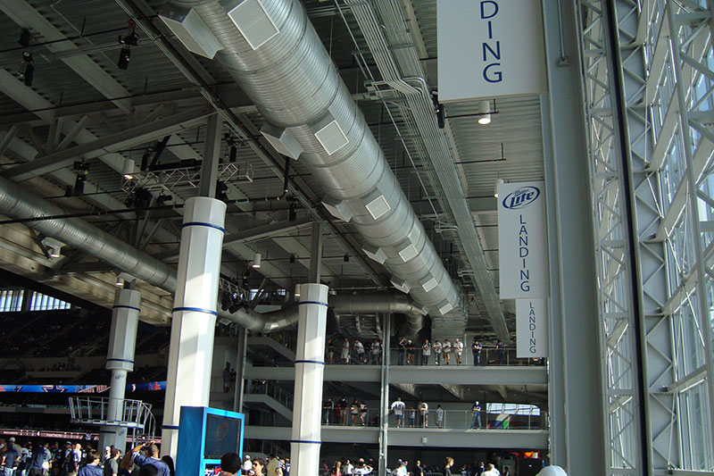
Cowboys Stadium
Dallas Cowboys Stadium concourse duct.
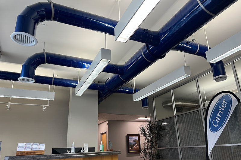
Spiral Round Duct in Building Interior
Exposed spiral round pipe in office building interior.
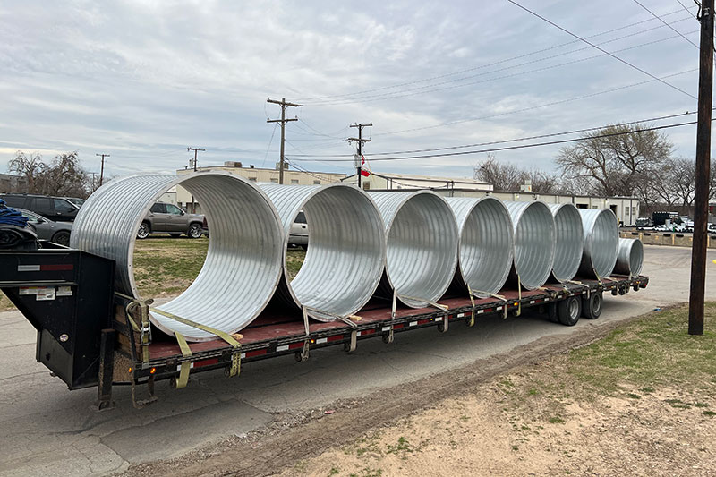
Spiral Duct on Trailer
Segments of spiral round pipe loaded on trailer, ready for transportation.
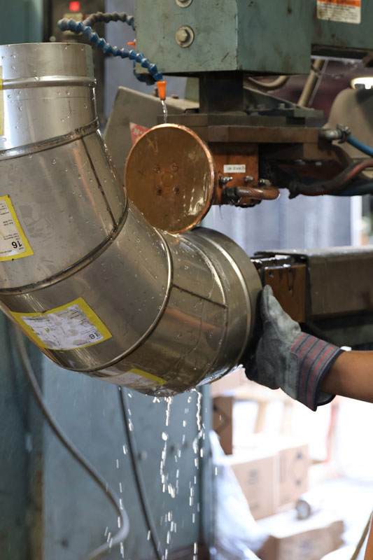
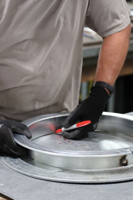
Welded Stainless Steel Gored Elbow
Seam welder allows for high quality weld and high volume.
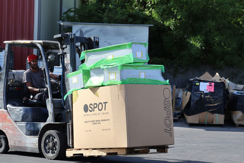
Shipping Crew
Each piece of duct is carefully loaded for shipment to your jobsite.
SPOT Fabricates Its Own Flanges
This helps us control fabrication time and allows for competitive pricing.
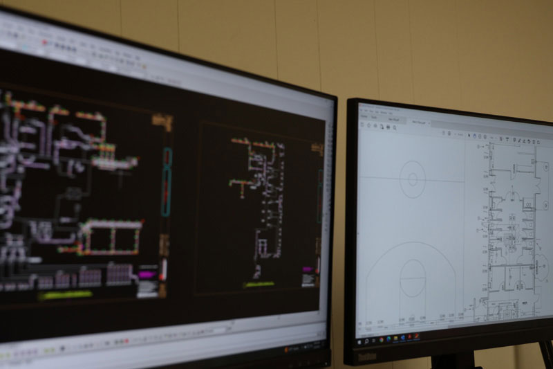
CAD / CAM Software
Before fabrication, pipe specifications are carefully planned using CAD/CAM software.
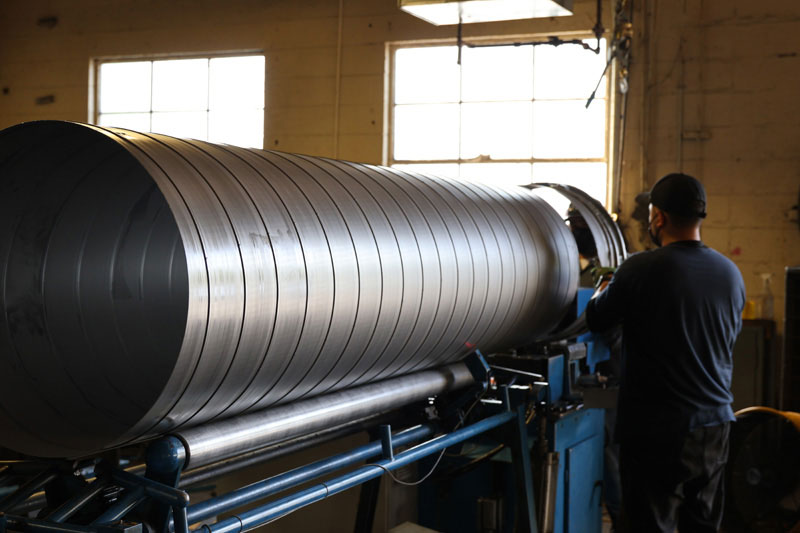
Spiral Pipe Fabrication
Each piece of spiral pipe is cut to length to save installation time in the field.
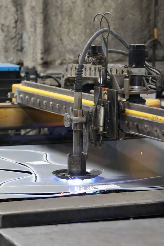
Plasma Torches Cut CAD/CAM Designed Parts for Each Job
Technology utilized to speed fabrication time and reduce material waste.
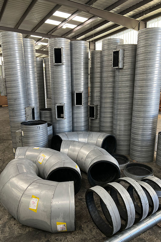
Galvannealled Spiral Duct and Fittings
Internally lined with factory mounted taps. Ready to be installed and painted.
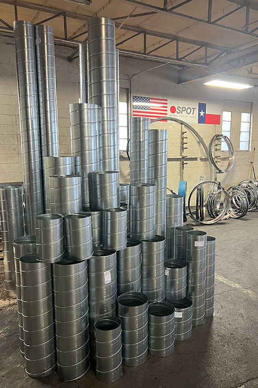
G90 Galvanized Spiral Duct
Cut to length to save the installing contractor time and money in the field.
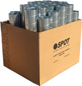
Spiral Pipe Short Joints
Loaded into SPOT box for shipping and job site storage.
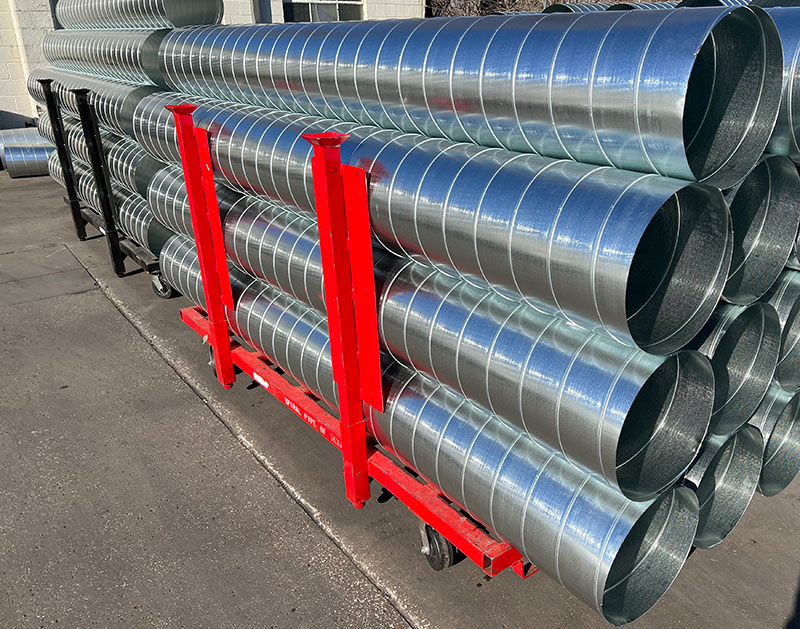
Galvanized Round Pipe
Galvanized spiral duct loaded onto rolling cart.


Product Type
SMACNA Standard
Single Wall/Double Wall
Resource Type
Spiral Pipe of Texas (SPOT) fabricates high quality, MADE IN THE USA sheet metal products for the heating, air conditioning and ventilation (HVAC) industries.